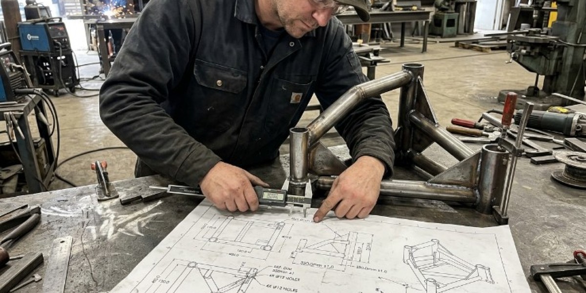

A custom metal project can change quickly when the design is not clearly communicated to the fabrication team. A small mistake in a dimension, hole location, material thickness, or joint position can affect cutting, welding, assembly, and installation. Fabrication drawings give the production team a clearer set of instructions before metal is processed.
Good fabrication drawings do more than show what a finished component should look like. They connect design details with the practical steps needed to build the part. Dimensions, materials, weld locations, part relationships, and other important information can be organized in one place so the project has a more consistent path from design to production.
What Are Fabrication Drawings?
Fabrication drawings are technical drawings prepared to show how a metal component or assembly should be manufactured. They can include dimensions, material specifications, component views, connection details, and other information needed to produce the finished item.
A drawing may represent one part or an entire assembly made from several sections. The level of detail depends on the project and the complexity of the component.
For custom projects, these drawings become especially useful because the finished part may not match any standard product. The fabrication team needs to know exactly what is being built and how the individual components are intended to fit together.
Clear drawings reduce guesswork and give different people involved in the project a common reference.
Why Are Fabrication Drawings Important?
Fabrication drawings help turn a design concept into practical production information. A basic sketch may explain the general idea, but it may not provide enough detail for accurate cutting, fitting, and welding.
A detailed drawing can identify critical dimensions, material thickness, hole locations, bend information, joint positions, and other features that affect production.
This becomes more important when several components need to work together. If one part is produced from different information than another, the final assembly may not line up properly.
Using a common drawing set helps keep the design, fabrication, and installation stages connected. That can reduce misunderstandings before work begins.
What Information Should a Metal Fabrication Drawing Include?
The information depends on the project, but important details commonly include part dimensions, material type, thickness, connection points, and views showing the component from different angles.
Critical features should be easy to identify. This may include mounting holes, slots, openings, bends, cut lines, joint locations, and dimensions that control how the part connects to other components.
Assembly drawings can also show how individual parts relate to each other. This is useful when a finished structure contains several brackets, plates, supports, or frames.
The purpose is not to fill a drawing with unnecessary information. The goal is to provide the details the fabrication team needs to produce the component accurately.
How Do Drawings Reduce Measurement Errors?
Measurements are one of the main sources of problems in custom fabrication. A component can be cut accurately and still be wrong if the original dimensions were incorrect.
A clear drawing provides a controlled reference for important measurements. Critical dimensions can be checked before material is cut, while related parts can be compared to make sure they are compatible.
This is particularly useful when a custom component needs to fit existing equipment. Mounting points and clearances can be documented so the fabricated part is designed around the actual installation.
Reviewing measurements at the drawing stage is usually easier than discovering a dimensional problem after the part has already been welded together.
How Do Fabrication Drawings Support Laser Cutting?
Laser cutting depends on accurate geometry. When a part includes detailed profiles, openings, mounting holes, or repeated shapes, the cutting process needs clear information about the intended dimensions.
Fabrication drawings can provide the basis for preparing those profiles. The geometry can be reviewed before the part moves into production, helping confirm that important features are positioned correctly.
This is especially valuable when multiple components need to match. If several brackets or plates are produced from the same approved design, the drawing provides a common reference for each part.
For projects involving detailed metal profiles, laser cutting can be incorporated after the design information has been reviewed and prepared for production.
Why Are Assembly Drawings Useful for Complex Projects?
An individual part drawing explains one component, but an assembly drawing shows how multiple components work together. This becomes useful when the finished product contains several welded or fitted pieces.
An assembly drawing can show the relationship between frames, brackets, plates, supports, panels, and other sections. This helps the fabrication team understand not only what each piece looks like but also where it belongs.
Assembly information can also help during installation. When the finished structure needs to be positioned around existing equipment, the drawing can provide a clearer reference for orientation and connection points.
For complex projects, part drawings and assembly drawings should support each other rather than being treated as separate documents.
How Do Drawings Help With Material Selection?
Material information is an important part of production. A drawing can identify the required material type and thickness so the fabrication team does not have to rely on assumptions.
This matters because different metals behave differently during cutting, welding, forming, and finishing. Changing the material can affect the weight, dimensions, fabrication process, and surface requirements of the finished component.
The drawing can also help distinguish between different material specifications when an assembly contains more than one type of metal.
Clear material information reduces the risk of fabricating a component from the wrong stock and discovering the issue later in the production process.
Why Should Weld Locations Be Shown?
Weld locations can affect the way a component is assembled and the order in which fabrication should take place. Showing the intended connections on the drawing gives the welding team a clearer understanding of the finished assembly.
The location of a joint can also influence access. A weld positioned behind another section may be difficult to complete or inspect after assembly.
Drawings can identify where parts connect and help the fabricator understand how the components should be fitted before welding.
This information is particularly useful for assemblies with several joints because the welding stage can then be planned around the complete structure rather than around individual parts.
Can Fabrication Drawings Help Control Tolerances?
Yes. A drawing can identify dimensions that are critical to the function or installation of a component. It can also distinguish them from dimensions where more flexibility is acceptable.
Not every feature needs extremely tight control. Requiring unnecessary precision can increase fabrication effort without providing a practical benefit.
For example, a mounting location may need closer control because it has to align with existing equipment, while a less critical outer dimension may allow more variation.
Documenting the required tolerances helps the fabrication team focus accuracy where it matters most and avoid unnecessary production work elsewhere.
How Do Drawings Improve Communication Between Teams?
Custom fabrication projects can involve designers, engineers, fabricators, installers, maintenance teams, and business owners. Each group may look at the component from a different perspective.
A clear drawing gives everyone a common reference. Instead of describing a feature only through messages or verbal instructions, the project can be discussed using a defined dimension, part number, location, or assembly view.
This can be especially useful when changes are made. A revised drawing can communicate the new information more clearly than a series of separate instructions.
Better communication reduces the chance that one team is working from outdated or incomplete information.
What Happens When Drawings Are Not Updated?
Changes are common during custom projects. Dimensions may be adjusted, materials may change, or a joint may be moved after an initial review.
If those changes are not reflected in the production drawings, the fabrication team may continue working from an earlier version. That can create parts that are accurate according to an outdated design but incorrect for the final project.
Version control is therefore important. The team should know which drawing is approved and whether earlier versions should no longer be used.
Keeping the design information current can prevent confusion when a project moves through multiple fabrication stages.
How Do Drawings Support Replacement Parts?
Replacement components often need to match equipment that already exists. The original part may be discontinued, damaged, or unavailable, so the new component must be created from measurements and design information.
A replacement drawing can document the current dimensions, mounting points, thickness, and other features needed to reproduce the part.
This becomes especially useful when the same replacement may be required again in the future. Instead of starting the design process from the beginning, the approved drawing can provide an established reference.
For older equipment, the drawing can also document any updates made to the original component. This creates a clearer record for future fabrication and maintenance.
Can Drawings Make Custom Metal Fabrication More Efficient?
They can improve efficiency by reducing uncertainty before production starts. When the fabrication team has clear dimensions and material information, fewer decisions need to be made during cutting and assembly.
This can reduce unnecessary trimming and adjustment. It can also help the team plan material use, part quantities, and fabrication sequence before the first component is produced.
Efficiency is not only about speed. A project that moves quickly but requires several corrections is not necessarily efficient.
A well-prepared drawing can help create a smoother workflow by giving each production stage the information it needs at the right time.
What Role Does Engineering Play in Fabrication Drawings?
Engineering helps connect the intended design with practical manufacturing requirements. A component may look correct in a concept drawing but still need changes before it can be fabricated efficiently.
Engineering review can consider material, dimensions, tolerances, joint locations, assembly methods, and installation conditions. This can reveal issues that may not be obvious from a simple visual design.
For custom projects, the drawing should reflect not only what the part is supposed to look like but also how it can realistically be produced.
When fabrication and engineering are closely connected, fabrication engineering can support the preparation and review of the information used before production begins.
How Do Drawings Help With Industrial Equipment?
Industrial components often need to fit into existing machinery and facility layouts. This makes accurate documentation especially useful.
A drawing can show mounting locations, dimensions, clearances, connection points, and the relationship between the new component and surrounding equipment.
This information can also support maintenance teams. Future technicians may need to understand how a custom bracket, support, enclosure, or frame was originally designed.
For factory projects, maintaining clear fabrication documentation can make future modifications and replacement work easier because the original design information is already available.
Why Should Existing Equipment Be Included in the Design?
When a new part is being created for an existing machine, the surrounding equipment becomes part of the design problem. A component that fits its own drawing may still fail to fit the actual machine.
Drawings should therefore be based on current measurements whenever possible. Old equipment may have been modified, repaired, or repositioned since the original installation.
Photos and site measurements can help confirm the current arrangement. The drawing can then be updated to reflect the actual equipment rather than relying only on historical information.
This approach is particularly helpful for custom replacement parts and equipment upgrades.
Can Fabrication Drawings Reduce Material Waste?
They can support better material planning by showing the final dimensions and quantities required for the project. Knowing the complete part list makes it easier to determine how the available stock should be used.
When several parts are required, drawings can help group components that share similar dimensions or material requirements. This can support more efficient cutting layouts.
Material waste can still occur because of part geometry, stock size, and required cutting spacing. The drawing does not eliminate scrap, but it provides the information needed to plan around those factors.
Accurate documentation also reduces the risk of wasting material on parts made to incorrect dimensions.
How Should a Fabrication Drawing Be Reviewed?
Start with the critical dimensions. Check overall size, mounting points, openings, connection locations, and any dimensions that affect installation or assembly.
Next, confirm material and thickness. Make sure these details match the intended component and the fabrication process planned for the project.
Then review the assembly relationship. Make sure individual pieces can actually fit together and that the joints provide practical access for fabrication.
Finally, compare the drawing with the real installation when the component is being designed for existing equipment. A drawing review is much more useful when it reflects actual site conditions.
What Are Common Problems With Poor Fabrication Drawings?
Missing dimensions are a common problem. Without enough information, the fabricator may have to make assumptions or request clarification before production can continue.
Conflicting dimensions can be even more difficult. If two parts of the drawing show different measurements for the same feature, the production team may not know which one is correct.
Another issue is outdated drawings. A revised design that is not clearly distributed can lead to parts being produced from an earlier version.
Poorly shown weld locations, missing material specifications, and unclear assembly relationships can also create avoidable fabrication problems.
How Can Businesses Improve Their Fabrication Documentation?
Start with one approved source of design information and keep the project documents organized. Each important part should have clear dimensions, material details, and identification.
Changes should be recorded and reflected in revised drawings. The team should be able to distinguish the current approved version from earlier drafts.
Photos and site measurements can be kept with the design information when the component is being fabricated for existing equipment.
For future replacements or modifications, keeping the final approved drawings can save time. The documentation becomes a useful record that supports later fabrication instead of allowing the same design work to start again.
Frequently Asked Questions
What is a fabrication drawing?
A fabrication drawing is a technical document that shows the information needed to manufacture a metal component or assembly, including dimensions, materials, connections, and other production details.
Why are fabrication drawings important?
They give the fabrication team a clear reference for producing the component and help reduce misunderstandings about dimensions, materials, joints, and assembly.
Do fabrication drawings include weld locations?
They can. Showing connection and weld locations can help the fabrication team understand how individual components should be fitted and joined.
Can fabrication drawings be used for replacement parts?
Yes. They can document the dimensions and construction details needed to reproduce a custom component for existing equipment.
Can laser cutting use fabrication drawings?
Yes. Detailed drawings can provide the geometry needed to prepare suitable components for laser cutting and later assembly.
How often should fabrication drawings be updated?
They should be updated whenever approved design changes affect production. The current version should be clearly identified so outdated information is not used.
Final Thoughts
Fabrication drawings provide a clear connection between design and production. They help define dimensions, materials, joints, tolerances, and assembly relationships before the first piece of metal is processed.
For custom projects, this information can reduce guesswork and make it easier to coordinate cutting, fitting, welding, finishing, and installation. It can also create a useful record for future repairs, replacements, and equipment modifications.
A well-prepared drawing does not replace good fabrication skills, but it gives those skills a clearer target. When the design information is accurate, current, and practical, the fabrication process has a stronger foundation and fewer reasons to rely on assumptions.